|
Interfacing the WSC-200B
Controller
for Illuminated Laser Warning Signs
(Click on picture to view enlargement.)
Use your "back" button to return to this page.
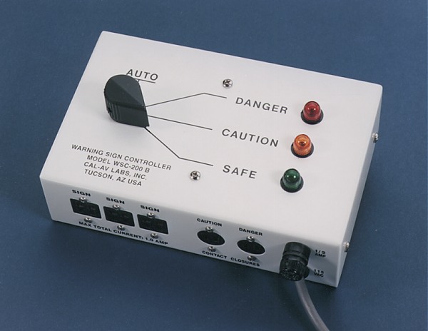
The WSC-200B controller provides power
to indicator lamps in one, two or three WS-100B, WS-1O1A, WS-102A, or WS-103A illuminated
warning signs. These warning signs serve to indicate to persons outside a hazardous area
the status of activities inside. Additionally, the controller provides for either manual
or automatic operation of the signs; the latter mode relying on signals from the
hazard-creating equipment, for example, an x-ray machine or a laser. This technical note
will offer some examples and suggestions to those responsible for connecting the WSC-200B
to other equipment.
Manual Operation
The WSC-200B produces 24-volts DC (rectified sine-wave),
both for the sign lamps and for its internal use. In the manual mode of operation, this
power is simply switched to the appropriate warning sign lamps (i.e. red, amber or green
to indicate "danger," "caution" or "safe"). For operation of
the sign system in the manual mode, the sign(s) must be connected to the controller and
the controller plugged in to a 115 volt 50-60 Hz outlet. No other connection is necessary
for manual operation. The sign system may be installed and operated in the manual mode
until necessary connections for automatic operation are made.
Automatic Operation
When operated in the automatic mode, the WSC-200B
normally provides power to the "safe" condition indicator lamps in the warning
signs. Two 2-contact connectors provide for two independent remote controls that switch
controller power from the "safe" lamps to the "caution" or to the
"danger" lamps. Within the WSC-200B, priority logic dictates that
"caution" overrides "safe" and that "danger" overrides
"caution." In the case, for example, of a laser laboratory where application of
power to the laser was used to activate the ''caution'' lamps and the laser ''beam-on
signal was used to activate the "danger" lamps, only the "danger"
lamps would light during "beam-on" operation, even though both the
"caution" and the "danger" signals were present.
Automatic operation is possible from single or multiple
signal sources, that is, more than one laser, power supply, switch, or what-have-you can
be paralleled such that any of them will activate the desired warning.
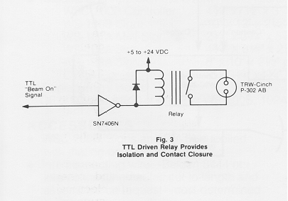
The signal required by the WSC-200B is a normally open
contact closure. If appropriate, a transistor or SCR pulldown may also be used,
particularly if the opto-isolated version thereof is necessary or advisable for isolation
of signal sources. In nearly all cases, a simple low-power relay will suffice as a means
of providing both the contact closure and isolation required. See interface circuits,
below.
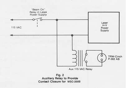
"Beam-on" Contact
Closure
A means of generating a contact closure during the
"beam-on" condition may be more involved, however, it is usually straightforward
and can be easily fabricated and installed by a competent electronics technician. The need
here is to find, preferably in the power circuitry, an electrical signal that is present
only during "beam-on." In most equipment there is some switch or relay that is
activated to supply power, control a shutter, etc. to enable the beam, turn on the high
voltage, etc.
An important point - any connection
between the WSC-200B and other equipment should provide electrical isolation, for example,
a separate set of contacts, a relay, an opto-isolator, etc.
In the case of a switch, a spare set of contacts may be
found, or the switch replaced with an equivalent type having one more set of contacts.
Alternatively, the switched power may be used to power a relay of low enough power
requirement that neither the switch nor power source is overloaded. Such small relays are
generally available in ac or dc versions with coil voltages of 6, 12, 24, 48, 115 and 220
volts. The minimum contact rating for any relay used to provide a contact closure for the
WSC-200B should be 1/2 ampere, inductive. In the case of a relay, it is likely that a low
power relay of the same coil voltage and frequency can be connected across it. Again, make
certain that the additional load of the added relay does not overload the switch,
transistor driver, power source, etc., that supplies the original relay.
Interface Circuits
Return
to Illuminated Laser Warning Signs Page
Installation
Instructions For Illuminated Warning Sign System
Two-wire cables are wired contact #1 to
contact #1, and Contact #2 to contact #2. Four-wire cables are wired with Each wire
connecting a numbered contact on a connector to its counterpart of the same number on the
other connector. (numbers can be seen inside connectors) if the installer Would like to
standardize on color coding (not necessary, but helpful) the following is recommended
(applies to Belden 8444):
|
|
|
SIGNAL |
|
1
|
0<--------BLACK----->0
|
1
|
Common |
|
2
|
0<--------GREEN----->0
|
2
|
+24 "SAFE" |
|
3
|
0<--------WHITE----->0
|
3
|
+24 "CAUTION" |
|
4
|
0<----------RED------->0
|
4
|
+24 "DANGER" |
4-Pin
Connector
(Viewing Wire-Attachment Surface of Male Plug)
|
PIN #1
|
_ _
|
PIN #3
|
|
PIN #2
|
| |
|
PIN #4
|
Return to Illuminated Laser Warning
Signs Page
 Top of Page Top of Page
Voice: 520.624.1300 | Email: Info@cal-av.com
CAL-AV LABS, INC.
2440 N. Coyote Dr, STE 116
Tucson, AZ 85745 USA
Mobile Antenna / Mast Spring Assemblies
Explosive Test Site & Range Instrumentation |
Special Projects
Home Page |
About CAL-AV |
How to Order
Copyright © 1997- CAL-AV Labs, Inc.
All rights reserved.
Web Design by CS Design Studios
|